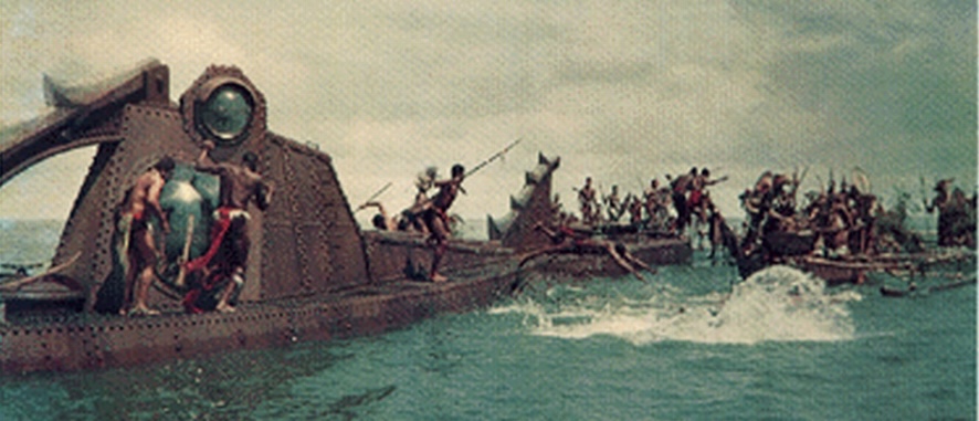

Ever since I first saw this movie in the early '60s, I have wanted to own my own model of this boat. I'm surprised that no one ever created a commercial kit of the Nautilus, but I guess this was before the age of over commercializing movies.
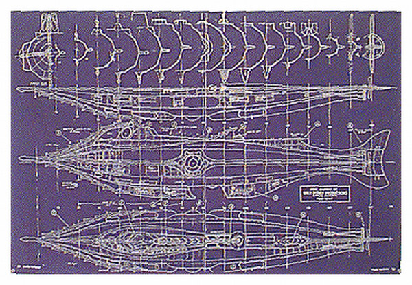
Anyway, I found some information and plans for the Nautilus in Scale Modeler around 1984. At that time I had access to a CAD/CAM system and I took those plans and built a 3D surfaces model from those plans. It took about 100 hrs to build and document that model. From that digital model I made a set of full size blue prints that I hoped to build a model from. The idea of building this model has laid around since then, the two biggest problems I had with taking on this project was reproducing the "teeth" and the rivets.
See related links at the bottom of this page for more sources of plans.
About November of 1997 I was surfing the web when I got the idea to look for model boat sites. It had been a few years since I had last built a model and all my catalogs were out of date. I wanted to lookup the addresses of these manufacturers as many had moved or blended together.
While I was looking that information over I came across a website for model submarines and from there I discovered another website that showed a completed model and listed a resource for parts to build this model. This site has moved, and I no longer have a source for these.
I bought the teeth and their set of plans (for comparison) and waited until August 1998 to start my model. In addition to the previously mentioned website, I found a site devoted to the Nautilus and the movie memorabilia that got me started collecting some of the old lobby cards, press books, posters and comic books that were issued with this movie.
Work begins
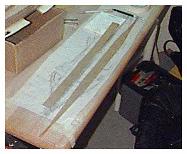
Having built several plank-on-frame models of sailing ships, I decided to use this basic approach to building the Nautilus. I cut a solid keel (vertical profile) of the submarine out of 1/4″ modelers plywood. Any of the sheets of plywood thinner than 1/4″ had too much flex and had already achieved a bow in the middle. The horizontal planes were also cut out of this plywood, and initially I was only going to cut the 2 halves, but I had forgotten that the horizontal planes on the Nautilus, start to rise about mid ship. The bulkheads were cut from 3/32″ bass wood.
The bulkheads had to be cut into 4 sections and the appropriate space removed for the keel pieces. All but the first and last bulkhead had sufficient mass to be cut in this way. At this stage I was beginning to realize that both ends of the model were going to be difficult to try and plank and build up.
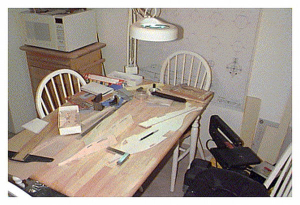
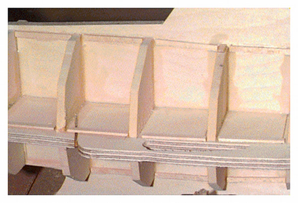
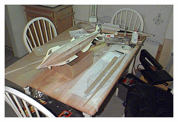
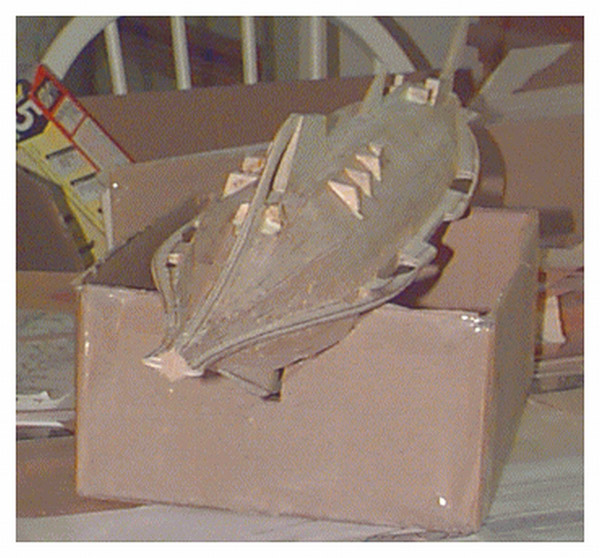
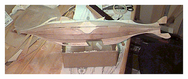
I used several small machinist's squares and 90 degree supports to help assemble these pieces. One side of the hull could be built directly on the keel, the other side had to be assembled separately. I used the side elevation taped down to the table top to help align the horizontal keel pieces and then to position the bulkhead parts. I built a quick cradle from a cardboard box to support the model while I work on it.
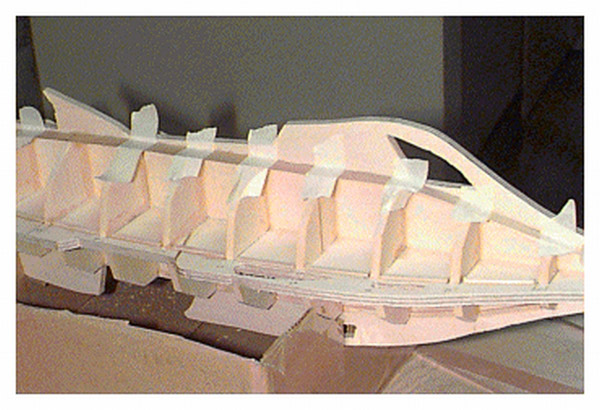
I need to determine how I will display this model when finished so I can design the proper supports for it. This photo shows the gap where the horizontal planes rise towards the bow. Also note the small 1/16 x 1/8″ basswood supports between the bulkheads.
Planking the Hull
The hull of the Nautilus is a 10 sided polygon of regular structure. I decided that I would use 10 planks (some split in two because of the keel and horizontal planes). I cut strips of 0.4mm modelers plywood slightly larger than the widest portion of each of these sides.
Each planking strip was then ruled down the center and the location of the bulkheads were laid in at 90 degrees to the center line.
The next step was then to measure the width of each face of the bulkhead and transfer it to the appropriate plank and bulkhead location. The width of each face was then divided in two and laid out from the center line of the plank. This produces a plank that gets skinny and fat at various locations along its length.
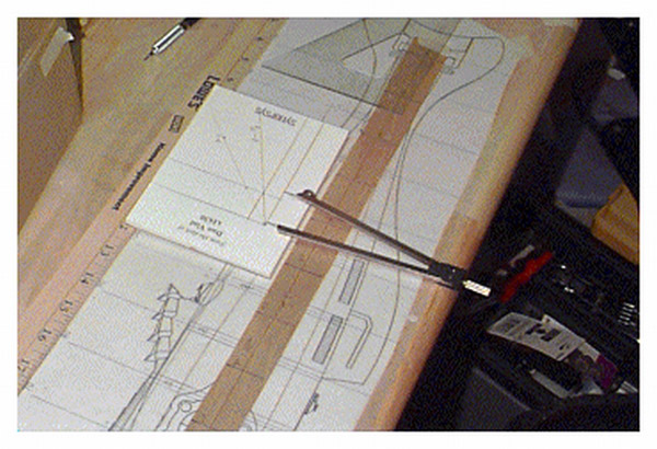
The following photos show a trick I learned as an illustrator for scaling or dividing a measured length into parts with just a set of dividers and a piece of paper.
In Photo 1 you see a pair of dividers on a piece of paper with a chart on it. The chart is simply a set of horizontal and vertical lines drawn perpendicular to each other. (Normally I would use a piece of grid paper for this.) From an intersection (0 point) I layout a 1 inch distance on the horizontal scale. On the vertical scale I measure the portion of the value I want to set (in this case I want 1/2 of the original value so I set it to 1/2″). The intersection of these two points is then connected to the 0 point or origin of the graph. The other diagonal in this picture is the 1 to 1 scale line or a line drawn through a point measured 1 inch on both the horizontal and vertical lines.
How to use this chart:
I simply take my measurement of the bulkhead face and place that on the horizontal axis (Photo 1), starting at the 0 point.
Then the other leg of the divider is swung up to the diagonal that represents the portion or division I wish to make. Since in this case I want to divide the value in half, I follow the appropriate diagonal line (Photo 2).
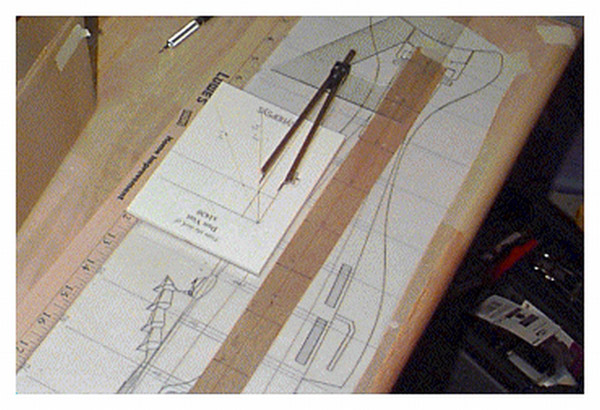
From the point that the divider crosses the diagonal I can now transfer that distance to the vertical axis and read the half value (Photo 3).
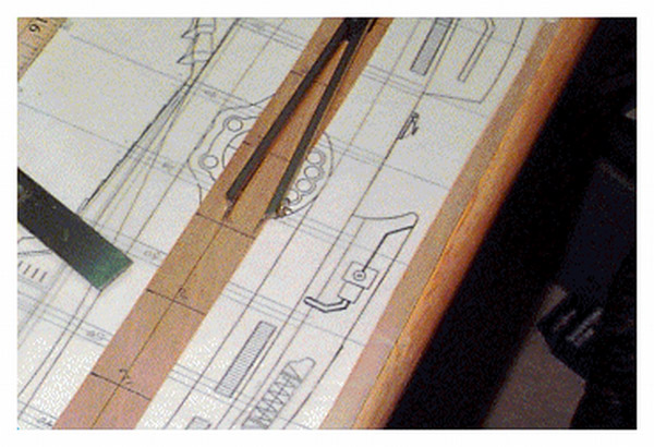
If I wanted to divide the original measure into thirds I would use the appropriate diagonal. This system can also be used to scale up a drawing or measurement, if you set the vertical portion greater than one, say 1.5 times the original measured value on the horizontal scale then you can achieve a scaled up version of the measurement. (Photo 4)
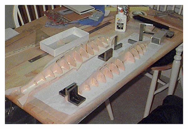
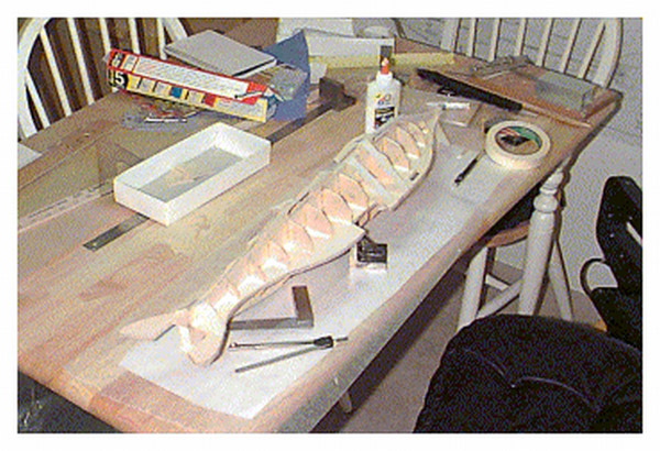
Next step is to start gluing the planks in place. I use a combination of Zap-A-Gap and regular white glue for this process. Zap-A-Gap is good for getting a quick initial positioning, but I like the white glue for permanence and strength.
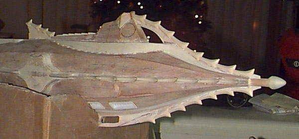
Superstructures and Fin Details
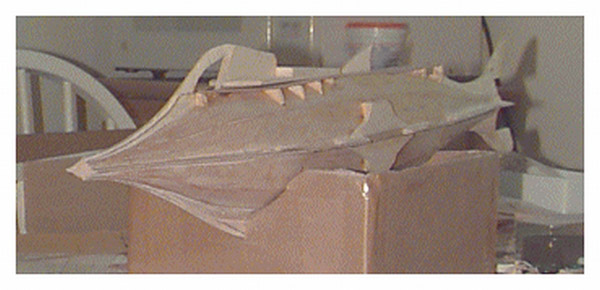
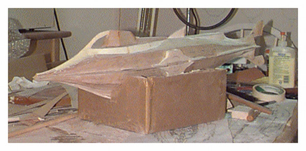
After planking the hull I started to thin and taper the various fins to their final form. I used a Dremel tool with an after market flexible shaft. This after an hour of so of work smoked, sputtered and died. I had to order a new Dremel tool, this time I went for the unit with the built in flexible shaft and it seems to be much better than the other combination.
I added supports (actually cut from the original frames). These supports will hold the plywood sheeting that will form the deck and the base for the control superstructure.
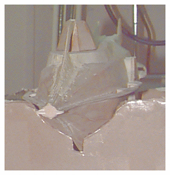
Adding the teeth and deck details
It has been a while since I updated my progress. This is now 11/27/98 and I have primarily added the teeth and some other detail parts.
I decided to mount the teeth, by drilling two holes in the base of each tooth and the fin where it was placed. In the holes I then inserted small modelers brass nails to add some strength.
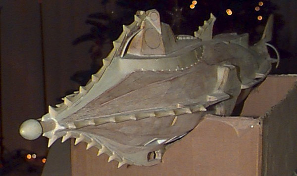
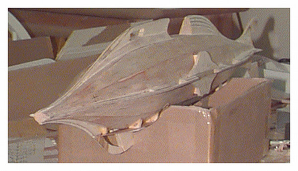
Completed Model
Here it is! The completed model. I finished this about the June 1st. The rivet details are small dowels (from a trunnel maker) each fitted into to a hole 0.031″ diameter and then clipped to the proper length. Close up these "rivets" are too large, but sit back a little bit and they give the right amount of texture.
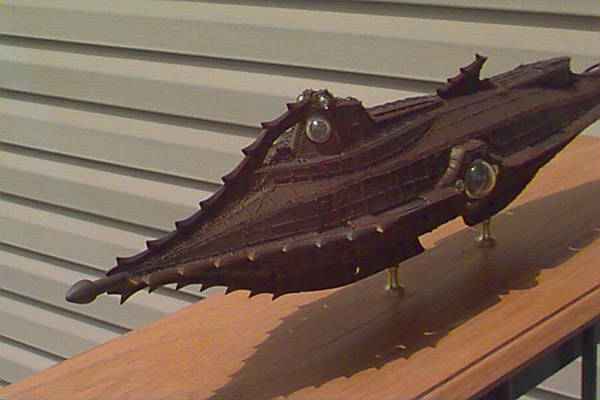
I spray painted the model with a Poly S Grimey Black and then applied a weathering finish of Rust all that gives the reddish tint. This is actually a transparent finish and in person some black does show through, but the photos registered the rust color more heavily.
Resources
- "20,000 Leagues under the Sea" at Oakland's Paramount Theater
- Visit to the Submarine Force Library & Museum Home of the USS Nautilus - Photos of the Disney Nautilus model in the lobby
- DisneySub.com - Complete set of plans for the submarine
Updates
Since building this model, I was contacted by the producers of "Hero Ships" for a segment on the USS Nautilus. They used my model when talking about Jules Verne's novel and his Nautilus. I haven't seen it yet on TV but I have seen the recording.
Disclaimer
This site is in no way shape, or form, virtual or real, sponsored, endorsed by, or affiliated with the Walt Disney Company, Euro Disney S.C.A., or Walt Disney Imagineering (formerly WED Enterprises). No infringement of any of their copyright is intended.